
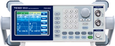
FGX-2220 is a full two-channel function generator of 20MHz by the DDS system.
Each channel separately can set all of the functions, such as waveform, frequency and amplitude.
Force and mechanical measuring equipment

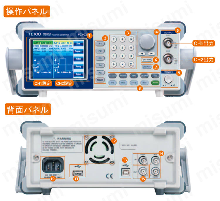
FGX-2220 is an Arbitrary Function Generator. 2 channels complete with frequency 20MHz Using DDS technology. Each channel can individually set all functions such as wave shape, frequency and amplitude.
The FGX-2220 supports multiple wave shapes (sine, square, ramp, pulse, noise) and transform features (AM, FM, PM, FSK).
FGX-2220 is a full two-channel function generator of 20MHz by the DDS system.
Each channel separately can set all of the functions, such as waveform, frequency and amplitude.
•DDS Function Generator series
•1μHz high frequency resolution maintained at full range
•20ppm frequency stability
•Arbitrary Waveform Capability
•Sine, Square, Ramp, Pulse, Noise, standard waveforms
•Internal and external LIN/LOG sweep with marker output
•Int/Ext AM, FM, PM, FSK, SUM modulation
•Burst function with internal and external triggers without marker output
•Store/recall 10 groups of setting memories
•Output overload protection
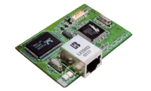
•USB interface as standard
•3.5 inch Color TFT LCD (320 X 240) graphical user interface
The specifications apply when the function generator is powered on for at least 30 minutes under +18°C to +28°C.
| FGX-2220 models | CH1 | CH2 | ||
| Waveforms | Sine, Square, Ramp, Pulse, Noise, ARB | |||
| Arbitrary Functions | ||||
| Sample Rate | 120 MSa/s | |||
| Repetition Rate | 60MHz | |||
| Waveform Length | 4k points | |||
| Amplitude Resolution | 10 bits | |||
| Non-Volatile Memory | 4k points | |||
| Frequency Characteristics | ||||
| Range | Sine, Square | 1uHz to 20MHz | ||
| Ramps | 1MHz | |||
| Resolution | 1uHz | |||
| Accuracy | Stability | ±20 ppm | ||
| Aging | ±1 ppm, per 1 year | |||
| Tolerance | ≤1 mHz | |||
| Output Characteristics | ||||
| Amplitude | Range | 1mVpp to 10 Vpp (into 50Ω) 2mVpp to 20 Vpp (open-circuit) |
||
| Accuracy | ±2% of setting ±1 mVpp (at 1 kHz,Sine wave) | |||
| Resolution | 1mV or 3 digits | |||
| Flatness | ±1% (0.1dB) ≤100kHz ±3% (0.3 dB) ≤5MHz ±5% (0.4 dB) ≤12MHz ±10%(0.9dB) ≤20MHz (sine wave relative to 1kHz) |
|||
| Units | Vpp, Vrms, dBm | |||
| Offset | Range | ±5 Vpk ac +dc (into 50Ω) ±10Vpk ac +dc (Open circuit) |
||
| Accuracy | 2% of setting + 20mV+ 0.5% of amplitude | |||
| Waveform Output | Impedance | 50Ω typical (fixed) > 10MΩ (output disabled) |
||
| Protection | Short-circuit protected Overload relay automatically disables main output |
|||
| Sine wave Characteristics | ||||
| Harmonic distortion | ≤-55 dBc DC to 200kHz, Ampl > 0.1Vpp ≤-50 dBc 200kHz to 1MHz, Ampl > 0.1Vpp ≤-35 dBc 1MHz to 5MHz, Ampl > 0.1Vpp ≤-30 dBc 5MHz to 20MHz, Ampl > 0.1Vpp |
|||
| Square wave Characteristics | ||||
| Rise/Fall Time | ≤25ns at maximum output. (into 50 Ω load) | |||
| Overshoot | 5% | |||
| Asymmetry | 1% of period +5 ns | |||
| Variable Duty Cycle | 1.0% to 99.0% ≤100kHz 10% to 90% ≤ 1MHz 50% ≤ 20MHz |
|||
| Ramp Characteristics | ||||
| Linearity | < 0.1% of peak output | |||
| Variable Symmetry | 0% to 100% (0.1% Resolution) | |||
| Pulse Characteristics | ||||
| Period | 40ns to 2000s | |||
| Pulse Width | 20ns to 1999.9s | |||
| Overshoot | <5% | |||
| Jitter | 20ppm +10ns | |||
| AM Modulation | ||||
| Carrier Waveforms | Sine, Square, Ramp, Pulse, Arb | Sine, Square, Ramp, Pulse, Arb | ||
| Modulating Waveforms | Sine, Square, Triangle, Upramp, Dnramp | Sine, Square, Triangle, Upramp, Dnramp | ||
| Modulating Frequency | 2mHz to 20kHz (Int) DC to 20kHz (Ext) |
2mHz to 20kHz (Int) DC to 20kHz (Ext) |
||
| Depth | 0% to 120.0% | 0% to 120.0% | ||
| Source | Internal / External | Internal / External | ||
| FM Modulation | ||||
| Carrier Waveforms | Sine, Square, Ramp, | Sine, Square, Ramp, | ||
| Modulating Waveforms | Sine, Square, Triangle, Upramp, Dnramp | Sine, Square, Triangle, Upramp, Dnramp | ||
| Modulating Frequency | 2mHz to 20kHz (Int) DC to 20kHz (Ext) |
2mHz to 20kHz (Int) DC to 20kHz (Ext) |
||
| Peak Deviation | DC to Max Frequency | DC to Max Frequency | ||
| Source | Internal / External | Internal / External | ||
| Sweep | ||||
| Waveforms | Sine, Square, Ramp, | Sine, Square, Ramp, | ||
| Type | Linear or Logarithmic | Linear or Logarithmic | ||
| Start/Stop Freq | 1uHz to Max Frequency | 1uHz to Max Frequency | ||
| Sweep Time | 1ms to 500s | 1ms to 500s | ||
| Source | Internal / External / Manual | Internal / External / Manual | ||
| FSK | ||||
| Carrier Waveforms | Sine, Square, Ramp, Pulse | Sine, Square, Ramp, Pulse | ||
| Modulating Waveforms | 50% duty cycle square | 50% duty cycle square | ||
| Modulation Rate | 2mHz to 100 kHz (INT) DC to 100 kHz(EXT) |
2mHz to 100 kHz (INT) DC to 100 kHz(EXT) |
||
| Frequency Range | 1uHz to Max Frequency | 1uHz to Max Frequency | ||
| Source | Internal / External | Internal / External | ||
| PM | ||||
| Carrier Waveforms | Sine, Square, Ramp | Sine, Square, Ramp | ||
| Modulating Waveforms | Sine, Square, Triangle, Upramp, Dnramp | Sine, Square, Triangle, Upramp, Dnramp | ||
| Modulation Frequency | 2mHz to 20kHz (Int) DC to 20kHz (Ext) |
2mHz to 20kHz (Int) DC to 20kHz (Ext) |
||
| Phase deviation | 0˚ to 360˚ | 0˚ to 360˚ | ||
| Source | Internal / External | Internal / External | ||
| SUM | ||||
| Carrier Waveforms | Sine, Square, Ramp, Pulse, Noise | Sine, Square, Ramp, Pulse, Noise | ||
| Modulating Waveforms | Sine, Square, Triangle, Upramp, Dnramp | Sine, Square, Triangle, Upramp, Dnramp | ||
| Modulation Frequency | 2mHz to 20kHz (Int) DC to 20kHz (Ext) |
2mHz to 20kHz (Int) DC to 20kHz (Ext) |
||
| SUM Depth | 0% to 100.0% | 0% to 100.0% | ||
| Source | Internal / External | Internal / External | ||
| External Trigger Input | ||||
| Type | For FSK, Burst, Sweep | |||
| Input Level | TTL Compatibility | |||
| Slope | Rising or Falling(Selectable) | |||
| Pulse Width | >100ns | |||
| Input Impedance | 10kΩ,DC coupled | |||
| External Modulation Input | ||||
| Type | For AM, FM, PM, SUM | |||
| Voltage Range | ±5V full scale | |||
| Input Impedance | 10kΩ | |||
| Frequency | DC to 20kHz | |||
| Trigger Output | ||||
| Type | For Burst, Sweep, Arb | |||
| Level | TTL Compatible into 50Ω | |||
| Pulse Width | >450ns | |||
| Maximum Rate | 1MHz | |||
| Fan-out | ≥4 TTL Load | |||
| Impedance | 50Ω Typical | |||
| Dual Channel Function | ||||
| Phase | -180˚ to 180˚ | -180˚ to 180˚ | ||
| Synchronize phase | Synchronize phase | |||
| Track | CH2=CH1 | CH1=CH2 | ||
| Coupling | Frequency(Ratio or Difference) | Frequency(Ratio or Difference) | ||
| Amplitude & DC Offset | Amplitude & DC Offset | |||
| Burst | ||||
| Waveforms | Sine, Square, Ramp | Sine, Square, Ramp | ||
| Frequency | 1uHz to 20MHz | 1uHz to 20MHz | ||
| Burst Count | 1 to 65535 cycles or Infinite | 1 to 65535 cycles or Infinite | ||
| Start/Stop Phase | -360˚ to +360˚ | -360˚ to +360˚ | ||
| Internal Period | 1ms to 500s | 1ms to 500s | ||
| GateSource | External Trigger | External Trigger | ||
| Trigger Source | Single, External or Internal Rate | Single, External or Internal Rate | ||
| Trigger Delay | ||||
| N-Cycle, Infinite | 0s to 655350ns | 0s to 655350ns | ||
| Frequency Counter | ||||
| Range | 5Hz to 150MHz | |||
| Accuracy | Time Base accuracy±1count | |||
| Time Base | ±20ppm (23˚C ±5˚C) after 30 minutes warm up | |||
| Resolution | The maximum resolution is: 100nHz for 1Hz, 0.1Hz for 100MHz. | |||
| Input Impedance | 1kΩ/1pf | |||
| Sensitivity | 35mVrms to 30Vrms (5Hz to 150MHz) | |||
| Save/Recall | ||||
| 10 Groups of Setting Memories | ||||
| Interface | ||||
| USB Host: USB Flash Drive USB Device : USB-CDC Class |
||||
| display | ||||
| 3.5”TFT LCD | ||||
| General Specifications | ||||
| Power Source | AC100 to 240V, 50 to 60Hz | |||
| Power Consumption | 25W (Max) | |||
| Operating Environment | Temperature to satisfy the specification: 18 to 28˚C Operating temperature :0 to 40˚C Relative Humidity: < 80%, 0 to 40˚C Installation category: CAT II |
|||
| Operating Altitude | 2000 Meters | |||
| Storage Temperature | -10 to 70˚C, Humidity: ≤70% | |||
| Dimensions | 266(W) x 107(H) x 293(D) mm | |||
| Weight | Approx. 2.5kg | |||
| Accessories | GTL-101 Quick Start Guide Power cord |
×2 ×1 ×1 |
||

Maintenance and calibration:
► We also have a calibration certificate included (optional)
► Please recalibrate after using for a certain period of time through our purchase store.
In Viet Nam: SEMIKI inc.

DISTRIBUTED BY:
Semiki instrumentation Co., Ltd
Email: sales@semiki.com
Office tel: +84 28 2253 3522
~DOING OUR BEST FOR YOU~
Electronic industry measuring machine

Electronic industry measuring machine

Electronic industry measuring machine

Electronic industry measuring machine

Electronic industry measuring machine

Electronic industry measuring machine
Multi-channel data logger, Electronic industry meter

Standard AC/DC programmable power supply, Electronic industry meter