| Model | Maximum Output Voltage [V] | Input Voltage [V] | Maximum I/O Current [A] |
Maximum I/O Power [W] |
AC input | ||
|---|---|---|---|---|---|---|---|
| 120 Vac ±10% 50 Hz/60 Hz single phase [A] |
200 Vac * ±10% 50 Hz/60 Hz single phase [A] |
230 Vac * ±10% 50 Hz/60 Hz single phase [A] |
|||||
| Input Current (typ.) | |||||||
| CD5-5-LThUs1 | 5 V | 1.5 to 5 V | 5 A | 25 W | 1 A | 0.5 A | 0.35 A |
| CD5-10-LThUs1 | 10 A | 50 W | 2 A | 1 A | 0.7 A | ||
| CD8-0.5-LLzThUs1 | 8 V | 0 to 8 V | 0.5 A | 4 W | 1 A | 0.5 A | 0.35 A |
| CD8-1-LLzThUs1 | 1 A | 8 W | 1 A | 0.5 A | 0.35 A | ||
| CD8-0.5-LThUs1 | 1.5 to 8 V | 0.5 A | 4 W | 1 A | 0.5 A | 0.35 A | |
| CD8-1-LThUs1 | 1 A | 8 W | 1 A | 0.5 A | 0.35 A | ||
| CD8-2-LThUs1 | 2 A | 16 W | 1 A | 0.5 A | 0.35 A | ||
| CD8-3-LThUs1 | 3 A | 24 W | 1 A | 0.5 A | 0.35 A | ||
| CD18-0.5-LThUs1 | 18 V | 1.5 to 18 A | 0.5 A | 9 W | 1 A | 0.5 A | 0.35 A |
| CD18-1-LThUs1 | 1 A | 18 W | 1 A | 0.5 A | 0.35 A | ||
| CD18-2-LThUs1 | 2 A | 36 W | 1 A | 0.5 A | 0.35 A | ||
| CD18-4-LThUs1 | 4 A | 72 W | 2 A | 1 A | 0.3 A | ||
| CD18-6-LThUs1 | 6 A | 108 W | 2.5 A | 1.3 A | 0.93 A | ||
| CD35-3-LThUs1 | 35 V | 1.5 to 35 V | 3 A | 105 W | 2.5 A | 1.3 A | 0.93 A |
* Option available soon
Sales of the following models ended on April, 2024. We continue to support the products.
| Model | Maximum Output Voltage [V] | Input Voltage [V] | Maximum I/O Current [A] |
Maximum I/O Power [W] |
AC input | ||
|---|---|---|---|---|---|---|---|
| 120 Vac ±10% 50 Hz/60 Hz single phase [A] |
200 Vac ±10% 50 Hz/60 Hz single phase [A] |
230 Vac ±10% 50 Hz/60 Hz single phase [A] |
|||||
| Input Current (typ.) | |||||||
| CD5-5-LUs1 | 5 V | 1.5 to 5 V | 5 A | 25 W | 1 A | 0.5 A | 0.35 A |
| CD5-10-LUs1 | 10 A | 50 W | 2 A | 1 A | 0.7 A | ||
| CD8-0.5-LLzUs1 | 8 V | 0 to 8 V | 0.5 A | 4 W | 1 A | 0.5 A | 0.35 A |
| CD8-1-LLzUs1 | 1 A | 8 W | 1 A | 0.5 A | 0.35 A | ||
| CD8-0.5-LUs1 | 1.5 to 8 | 0.5 A | 4 W | 1 A | 0.5 A | 0.35 A | |
| CD8-1-LUs1 | 1 A | 8 W | 1 A | 0.5 A | 0.35 A | ||
| CD8-2-LUs1 | 2 A | 16 W | 1 A | 0.5 A | 0.35 A | ||
| CD8-3-LUs1 | 3 A | 24 W | 1 A | 0.5 A | 0.35 A | ||
| CD18-0.5-LUs1 | 18 V | 1.5 to 18 V | 0.5 A | 9 W | 1 A | 0.5 A | 0.35 A |
| CD18-1-LUs1 | 1 A | 18 W | 1 A | 0.5 A | 0.35 A | ||
| CD18-2-LUs1 | 2 A | 36 W | 1 A | 0.5 A | 0.35 A | ||
| CD18-4-LUs1 | 4 A | 72 W | 2 A | 1 A | 0.3 A | ||
| CD18-6-LUs1 | 6 A | 108 W | 2.5 A | 1.3 A | 0.93 A | ||
| CD35-3-LUs1 | 35 V | 1.5 to 35 V | 3 A | 105 W | 2.5 A | 1.3 A | 0.93 A |
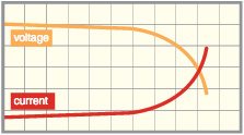
By setting both of current value and voltage value, the output exceeding the value you set can be disabled.
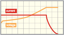
The charge is carried out at the current value you set. Even if the terminal voltage changes during charge, a constant current can be passed.
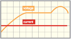
The charge is carried out at the voltage value you set. Even if the charge current changes, a constant voltage can be applied.
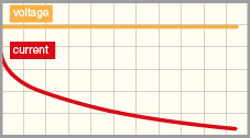
The discharge is carried out at the current value you set. Even if the terminal voltage changes during discharge, a constant current can be passed.
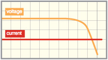
The discharge is carried out at the resistance value you set. The value of terminal voltage is measured and the current value for discharge is decided according to the setting value.
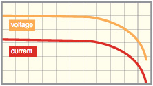
The discharge is carried out at the power value you set. If the terminal voltage changes during discharge, constant power can be consumed according to the change.
| Control function | ON/OFF setting, Charge/Discharge operation switching, Charge/Discharge mode switching | |
|---|---|---|
| Various status displays (Charge/Discharge status, Operation mode: OVP, OCP, UVP, OPP, OTP, OHP, OBP, ACF, RS) | ||
| Collective control when multiple devices are connected | ||
| Setting function | I/O voltage setting, I/O current setting | Voltage/Current value mode (maximum rated voltage/current value) |
| OVP/OCP/UVP/OPP setting | Voltage/Current power value mode (maximum overvoltage/overcurrent/over discharge/over power protection value) | |
| Constant power/Constant resistance setting | Power value mode (maximum rated power value), Resistance value mode (0.2 Ω to 18 kΩ) | |
| Reading function | I/O voltage measurement, I/O current measurement | Voltage/Current value mode (maximum rated voltage/current value) |
| I/O voltage setting value, I/O current setting value | Voltage/current value mode (maximum rated voltage/current value) | |
| OVP/OCP/UVP/OPP setting | Voltage/Current power value mode (maximum overvoltage/overcurrent/over discharge/ over power protection value) | |
| Constant power/Constant resistance/ Temperature setting value |
Power value mode (maximum rated power value), Resistance value mode (0.2 Ω to 18 kΩ), Temperature value mode (0 to +100°C) | |
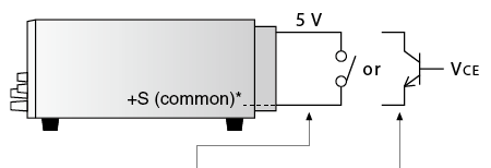
| OUTPUT | Relay | Open collector |
|---|---|---|
| ON | SHORT | VCE 0.4 V or less |
| OFF | OPEN | VCE 2 V or more |
Sink current 1 mA
* As +S is set to common, input the external control voltage based on +S. Otherwise, a failure may be caused.
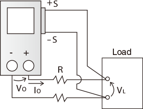
The voltage reduction (VO-VL) due to resistance (R) of the output line and degradation of stability due to contact resistance are prevented (up to 0.5 V).
For the charge-discharge tests, various protection functions are prepared for protecting your devices and this unit.
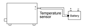
The temperature of a battery is measured by the temperature sensor. If the temperature becomes abnormal, charge and discharge are stopped in an urgent manner to protect the battery.
digital interface board
Digital control with LAN/USB/RS-232C/RS-485/GPIB is available.
-LGmb devices connected in a daisy chain can control up to 16 units.
* As for the option, USB interface is not attached.
* For more information on the digital interface, refer to CO/USB series datasheet.
A separate adapter (sold separately) is required for connection. For details, click here.
carrying handle
The carrying handle is attached to the upper surface. (only the model of dimension diagram C of datasheet)
200 Vac ±10% input on sale soon
For the input current, refer to the “MODELS”.
230 Vac ±10% input on sale soon
For the input current, refer to the “MODELS”.
For Model No. please be sure to contact the sales representative.
To use Matsusada Precision’ s digital interface, you need to prepare a digital interface adapter saparately. The following interface adapters are available according to your controller port.

| Standard Except for -L(200V), -L(230V) option |
CABLE TYPE1 | 125 V / 10 A | 2.5 meters Fixed length |
||
|---|---|---|---|---|---|
| Standard For -L(200V), -L(230V) option |
CABLE TYPE3 | 250 V / 10 A | 2.5 meters Fixed length |
||
| Sold separately | CABLE TYPE4 | 250 V / 10 A | 2.5 meters Fixed length |
Convenient for a single use for an individual device.
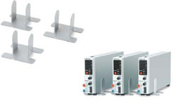
10 units * /1 shelf are stored in the cabinet and each unit can be removed easily. [* 1.38-inch wide models]

CD-BC is dedicated software for remote-controlling our company’s charge-discharge power supply. It realizes ideal power supply control when you carry out the charge-discharge test for various rechargeable batteries such as lithium-ion batteries. It enables the setting of test conditions, test execution, confirmation of test status, and display and saves test results.
* “CD-BC” is only controlling one channel version. If you want to control multiple channels, you need to purchase the CD-BC-512 ch.
Create a condition for charge and discharge.
Up to 16 patterns of charge and discharge sequence can be set. You can set various test conditions according to purpose such as selection of charge and discharge mode and setting of each protection function.
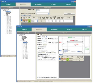
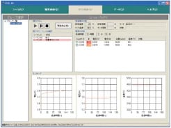
Execute the test for each group you set.
On the execution screen, necessary information such as sequence, thermostatic chamber, the status of power supply, voltage value, and current value at test can be monitored on one screen. If the test is executed for multiple groups at the same time, the statuses can be collectively monitored.
Check the completed test data. You can check the data for each cycle of the sequence. You can check the status for each unit time and end condition of each cycle.
The data can be displayed as a graph.
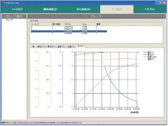
* It does not guarantee the operation.
| OS | Windows 10 (32/64 bit), 8.1 (32/64 bit), 8 (32/64 bit), 7 (32/64 bit), Vista (32/64 bit), Microsoft .NET Framework4.0SP1 | ||||||
|---|---|---|---|---|---|---|---|
| Language | English/Japanese | ||||||
| CPU | Pentium4 or more | ||||||
| RAM | 1 GB or more | ||||||
| HDD | 500 MB or more free capacity | ||||||
| Monitor | 1024 x 768 or more resolution | ||||||
| Connection port | USB port or COM port is required depending on the connection. | ||||||
| USB port | 1 port or more (When using CD-BC-512ch, USB protection key connection is required.) | ||||||
Maintenance and calibration :
► We also have calibration certificate attached ( optional )
► Please re-calibrate after use for a certain period through our purchase store. Local Vietnam : SEMIKI CORP

DISTRIBUTED BY:
Semiki instrumentation Co., Ltd
Email: sales@semiki.com
Office tel: +84 28 2253 3522
~DOING OUR BEST FOR YOU~